
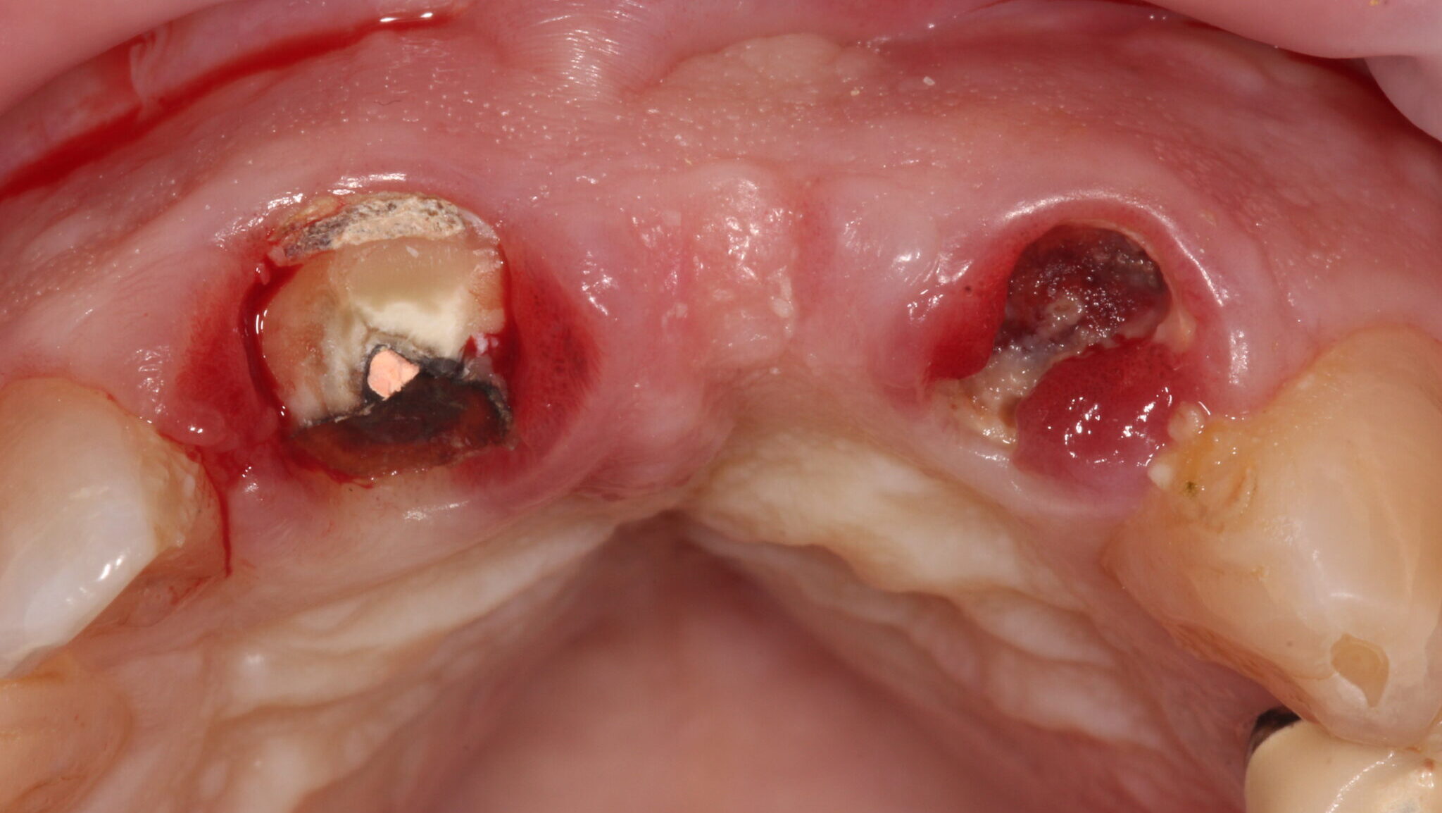

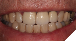
A 75-year-old male patient developed a problem with a tooth supported bridge for the upper right central and left central and lateral incisor teeth that had been in situ for more than twenty years. One of the supporting teeth had become loose and the referring dentist noticed the upper left abutment tooth was grossly carious and the three-unit bridge entirely supported by the upper right central incisor tooth.
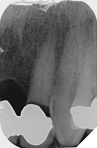
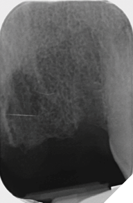
Radiographic examination shows the upper left lateral incisor tooth has decayed through and through and the upper right central incisor tooth is heavily root treated and filled (Figs. 1-2).
Fig. 1
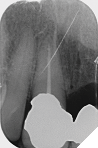
Fig. 2
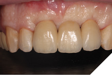
The existing metal ceramic bridgework was thick and bulky, but the patient was used to it. The patient also didn’t have any pain or discomfort yet from the slightly loose bridge or dental caries. The patient was most concerned the bridge would suddenly come out and would have a space (Figs. 3-4).
Fig. 3
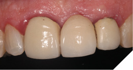
Fig. 4
Treatment planning
The patient understood that the upper left lateral tooth was beyond repair due to the depth of the tooth decay. We also discussed the upper right central tooth had a very poor long-term prognosis due to the extent and depth of the amalgam restorative core. The patient was aware that the bridge could fracture at any time, and he could be left with a large anterior space – so we planned an immediate acrylic partial denture for the short-term loss of the anterior bridge and teeth (Figs. 5-7).
Fig. 5
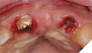
Fig. 6
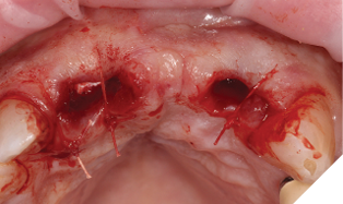
Fig. 7
- Extraction of upper right central and left lateral incisor teeth and immediate fit of acrylic partial denture.
- I suggested a delayed immediate placement protocol to allow for full soft tissue coverage of the extraction sites and maturation with early hard tissue healing of the alveolus.
- Simultaneous contour ridge augmentation with a long-term substitution rate biomaterial was planned for optimal aesthetics and protection of the autogenous buccal plate covering the implant.
We discussed improving the aesthetics of the tooth supported bridge and felt a staged approach would give us the opportunity to increase hard and soft tissue volumes with a relatively minimally invasive approach and avoid the need for unnecessary connective grafts.
Straumann Bone level tapered implants were planned:
- UR1 with a 4.1mm x 10mm regular connection
- UL2 with a 3.3mm x 10mm narrow connection cerabone® xenograft particulate and Jason® membrane were my preferred biomaterials of choice to augment the ridge due to their proven clinical track record and scientific evidence-based background.
Surgical and prosthetic procedure
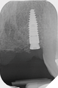
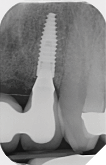
Eight weeks after extraction of the UR1 and UL2 we radiographically assessed the hard tissue healing. The soft tissues had matured well, with good volume of keratinized mucosa and we felt it appropriate to proceed with the implant placements (Figs. 8-9).
Fig. 8
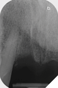
Fig. 9
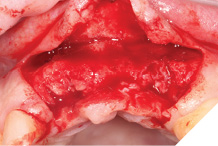
A Papilla sparing extended H-shaped crestal incision was made, full thickness mucoperiosteal flap with clean reflection of the periosteum. The healing alveolar sockets were exposed and used to guide our planned dental implant placements. An initial periosteal release was carried out to allow passive tension free closure (Figs. 10-12).
Fig. 10
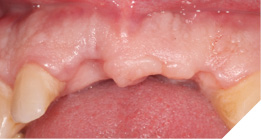
Fig. 11
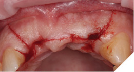
Fig. 12
Straumann Bone Level tapered implants were placed as per the planning above and following the Straumann drill placement protocol. We collected the autogenous bone chips from the flutes of the drills as part of the osteotomy site preparation.
Full Depth Direction Indicators were used to check correct implant angulations for screw retained restorations. The implants were almost wholly within autogenous alveolar bone – however we clearly needed to reinforce and thicken the buccal profile for long-term implant health and gingival stability (Figs. 13-18).
Fig. 13
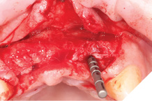
Fig. 14
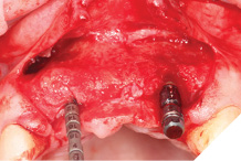
Fig. 15
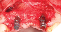
Fig. 16
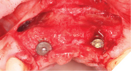
Fig. 17
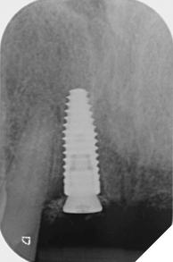
Fig. 18
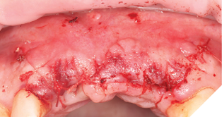
The autogenous bone chips collected were applied to any exposed implant threads and Cerabone was then placed buccally to reinforce and increase hard tissue volume. Jason membrane was used to cover the augmented region and further periosteal relieving incisions were made to ensure tension free closure.
The surgical site was closed with a series of simple interrupted Vicryl Rapide sutures for ease of patient comfort and convenience (Figs. 19-21).
Fig. 19
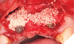
Fig. 20
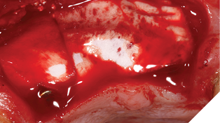
Fig. 21
The site was allowed to heal uninterrupted for 10 weeks. This time period was chosen because the implants were almost wholly within autogenous bone and therefore, we can assume osseointegration is almost complete.
Small H-shaped incisions were made over the implant fixtures to enable access to position Mono-Scan bodies to allow a digital 3 shape scan of the implants in situ in relation to each other, adjacent and opposing teeth. We then planned to fabricate a provisional bridge to develop aesthetic soft tissue profiles (Figs. 22-24).
Fig. 22
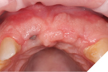
Fig. 23
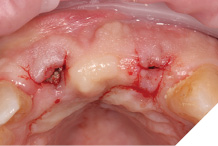
Fig. 24
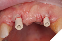
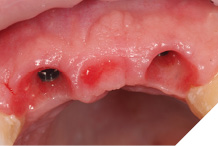
A larger healing abutment was placed on the UR1 fixture to allow further healing but to prevent the risk of losing buccal keratinized mucosa a smaller healing abutment was used on the UL2. Which meant at 3 weeks later when we came to fit the provisional bridge, we had to re-expose the fixture head. We also used a small 3mm soft tissue biopsy punch on the UL2 site to widen the initial emergence profile and allow passive fit of the provisional bridge. The model was socket by 1mm to allow the pontic site to be developed and allow modification of the profile (Figs. 25-28).
Fig. 25
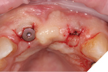
Fig. 26
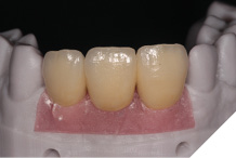
Fig. 27
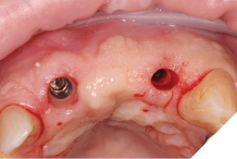
Fig. 28
After 8 weeks to allow maturation of the soft tissue profile a new digital scan was taken with modified scan bodies to capture the now unique emergence profiles. The soft tissue profile was very stable (Figs. 29-30).
Fig. 29
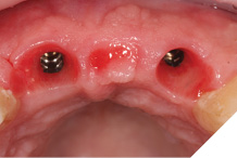
Fig. 30
The definitive metal ceramic bridge was fabricated with the new soft tissue emergence profiles. The framework was fabricated by Creates and due to the short nature of the span we felt the intraoral scan was sufficiently accurate without the need for a verification jig to ensure passive framework fit into the implant fixtures. The ceramic work was optimally shaped for cleans ability and long-term soft tissue adherence and maintenance.
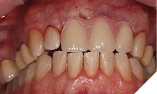
The definitive bridge was fitted and torqued in situ uneventfully after such excellent healing of the provisional bridge (Figs. 31-37).
Fig. 31
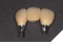
Fig. 32
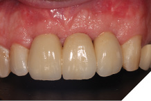
Fig. 33
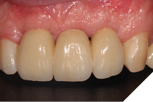
Fig. 34
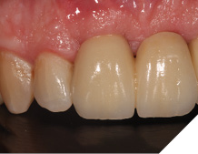
Fig. 35
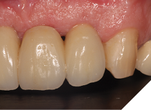
Fig. 36
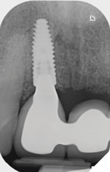
Fig. 37
Final result
The definitive bridge has integrated well and both hard and soft tissue healing has gone well and very predictably. The chosen biomaterials have integrated well and healed exactly how we would expect them to. The patient was very happy with the aesthetic result especially when we consider what he had been used to preoperatively. The function and phonetics met the patient’s expectations and overall, we were all very happy with the result.
Conclusion
The replacement of the failing tooth supported metal ceramic bridge with an implant supported screw retained prosthesis followed a very predictable treatment plan. The delayed placement of the implants allowed us to increase the volume of keratinized mucosa and the use of biomaterials that integrate and handle as we need them to, allows us to recontour the alveolar ridge.
The predictable nature of the cerabone® and Jason® membrane biomaterials used, and their inert immunological properties ensure that the gingival tissues can heal in such a way that they remain pink and healthy. 
Oral Health welcomes this original article.
Disclosure: The author declares that he has no financial interests, either directly or indirectly, in the products or information associated with this manuscript.
About the author

Dr. Cutts graduated from Guy’s Hospital, London, in 2000 and has studied implant dentistry across the UK, Europe and North America and has a Diploma in Implant Dentistry from the Royal College of Surgeons, London. He is a committed fellow of the International Team for Implantology (ITI) – and a Study Club director and clinical mentor. As well as being a Fellow of the ITI, he is also a member of the Associated of Dental Implantology (ADI) and the Royal College of Surgeons (RCS). His commitment to cosmetic dentistry maintains his full membership of the British Academy of Cosmetic Dentistry (BACD). He lectures nationwide on a variety of topics, but has a particular interest in aesthetic implant dentistry.