

The integration of immediate dental implants with provisional restorations is a technique that addresses both functional and aesthetic concerns, particularly in the anterior region where appearance is critical. The traditional protocol for dental implant placement involves a healing period between tooth extraction and implant insertion. Advances in implantology have allowed for immediate implant placement and provisionalization, potentially reducing treatment time and providing immediate aesthetic outcomes. This approach is particularly advantageous in the anterior region where esthetics are crucial. Utilizing the extracted natural tooth as a provisional restoration can enhance the aesthetic result while maintaining soft tissue contours. This case report presents a novel application of immediate anterior implant placement with immediate provisionalization using the extracted tooth.
Case description
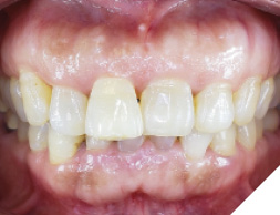
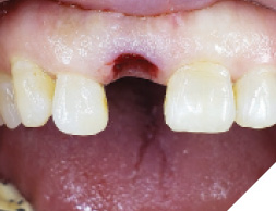
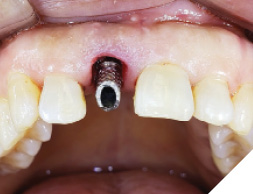
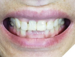
A 55-year-old, ASA-1 female patient presented with a non-restorable central incisor (tooth #11) due to periodontal involvement. Her main complaint was that the tooth was forwardly placed and moved when she pushes it with her tongue. Patient had no relevant medical history and denied any medical condition or allergies. The patient was aesthetically conscious of her smile because of the bucally positioned #11. Orthodontic therapy was not an option due to severe root resorption and after a detailed consult, the patient agreed to an extraction with immediate implant therapy. Clinical and radiographic evaluations presented that the patient has a high smile line (Fig. 1) with a buccally positioned #11 with a diastema between the right maxillary central incisor and the lateral incisor (Fig. 2). Comprehensive clinical and radiographic assessments were conducted. Adequate bucco-palatal ridge width with keratinized tissue was observed.
Fig. 1
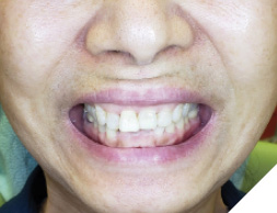
Fig. 2
Treatment plan:
Extraction + immediate implant (non-guided – freehand placement) and temporization utilizing the clinical crown of the #11.
Wait for osseointegration period of 4 months and restore with a single screw retained crown with a customized titanium abutment.
The plan included restoring the central maxillary incisor in line with her occlusal arch form maintaining the same gingival zenith and closing the diastema with the right lateral incisor.
Surgical procedure (Step 1)
Pre-surgical antibiotics were prescribed, Amoxicillin 2grams, 1 hour prior to the surgery, and to continue three times a day for the next 10 days. Ibuprofen 400mg, 1 tablet, 1 hour prior to surgery and to continue 1 tablet every 4 to 6 hourly for 3 to 5 days with food.
Chlorhexidine 0.12% was prescribed as a mouth rinse for 2 weeks post-surgery.
Pre-surgical preparation (patient was advised to brush her teeth, scrap her tongue thoroughly and rinse for 30 seconds with a cup of 0.12% chlorhexidine gluconate), local anaesthesia with 2% lidocaine and 1:100,000 epinephrine was administered as buccal and palatal infiltration with 1 carpule.
Tooth #11 was extracted using a simple forcep and severe root resorption of the incisor was noted (Figs. 3 & 4).
Fig. 3
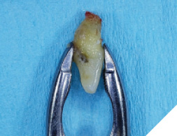
Fig. 4
The initial pilot osteotomy was prepared along the palatal wall using a lance drill at 1200RPM and sterile saline irrigation. The osteotomy was widened with a 2.2 dia drill at 8.5mm depth.
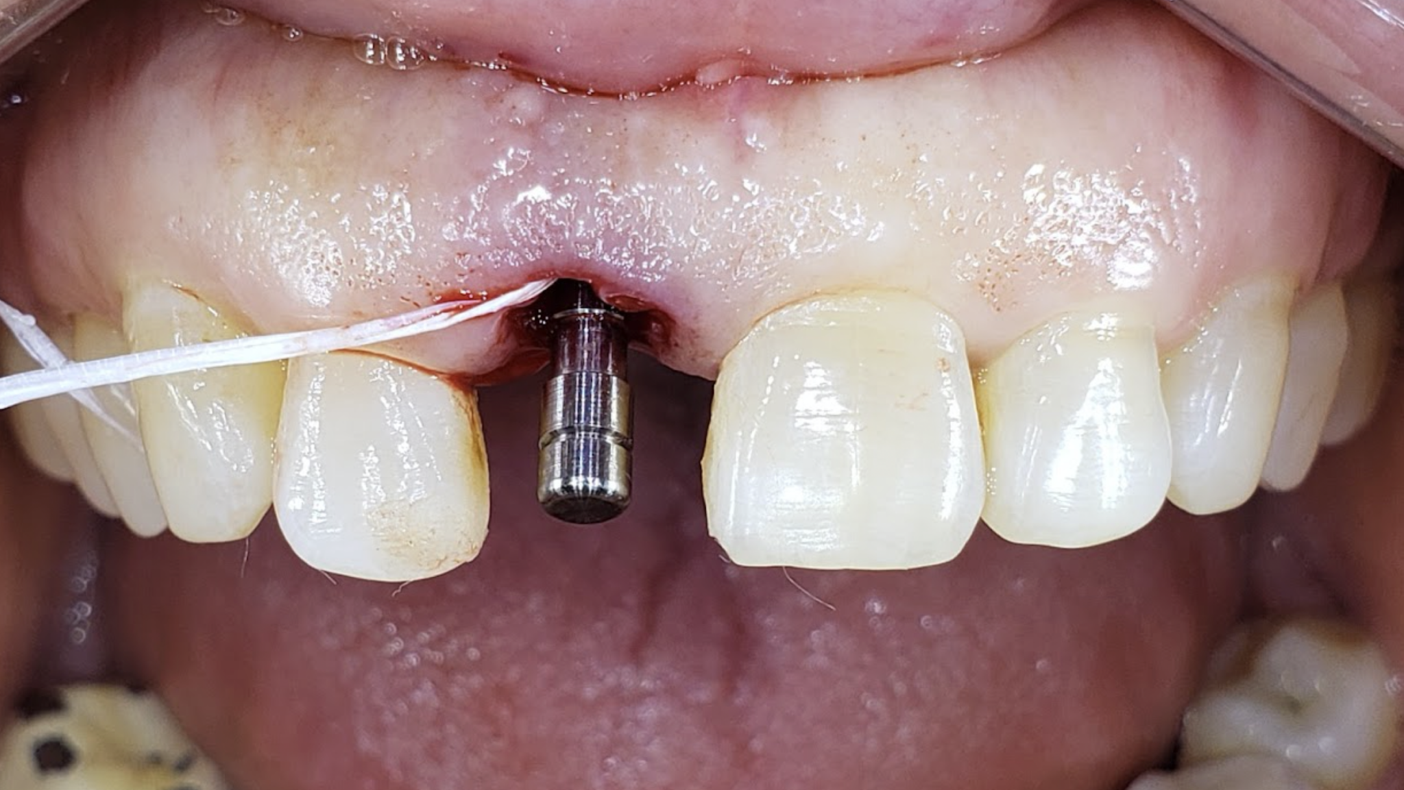
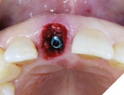
A guide pin secured with dental floss was placed into the osteotomy site (Fig. 5) and an intra oral periapical radiograph was taken (Fig. 6). The radiograph confirms parallelism with adequate distance between the adjacent tooth roots not impeding into any anatomic structure. The final osteotomy was completed with a 3.5mm diameter drill at 11.5mm length. Thorough sterile irrigation with debridement of the site was performed prior to implant placement. One can observe the osteotomy was prepared within the palatal host native bone allowing for minimal exposure of implant threads at the crest (Fig. 7). A Hiossen ET 3 implant 4.0x 11.5 was placed with adequate primary stability at 35ncm (Fig. 8). Once the implant fixture had been placed in an adequate 3D position utilizing the implant mount to help visualize angulations, the mount was then removed and replaced with a cover screw (Fig. 9). An intra oral radiograph (Fig. 10) was taken to confirm the final position of the implant fixture. The jump gap was more than 2mm and was carefully filled with small particulate sized allograft of cortico-cancellous nature (Fig. 11).
Fig. 5
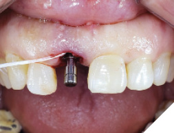
Fig. 6
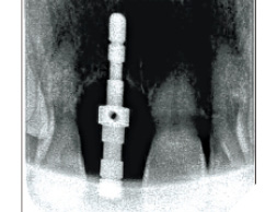
Fig. 7
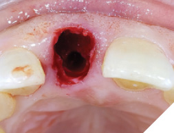
Fig. 8
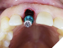
Fig. 9
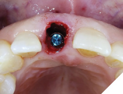
Fig. 10
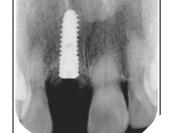
Fig. 11
The patient was then given some time of rest, meanwhile the extracted tooth (Figure 12) was then modified chair side (Fig. 13) where the root was cut out and the clinical crown was hollowed out allowing it to be converted into a temp shell for a pick up with a temporary titanium abutment (Fig. 14). The temp titanium abutment was modified and tried intra orally (Fig. 15) and the “temp shelled” clinical crown was acid etched with 37% phosphoric acid, single bottle bonding system was used, light cured and placed over the temp abutment intraorally. Flow composite was utilized to fill in the space between the titanium abutment and clinical crown and light cured.
Fig. 12
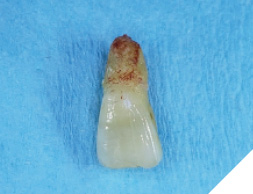
Fig. 13
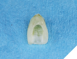
Fig. 14
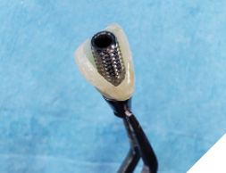
Fig. 15
This was then unscrewed from the mouth, finished and polished to create a screw retained temporary restoration (Fig. 16). This restoration was cleaned and reinserted into the implant, then after verifying occlusion and inter proximal contacts (Fig. 17), a radiograph was taken to confirm seating of the temp restoration (Fig. 18). A very mild discrepancy was noted in the gingival zenith of the right and left maxillary central incisor.
Fig. 16
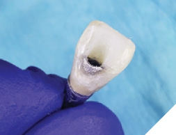
Fig. 17
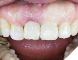
Fig. 18
At the 2 week follow up, the soft tissue had healed well (Fig. 19), and the patient was satisfied with the outcomes with good aesthetics (Fig. 20).
Fig. 19
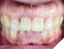
Fig. 20
Prosthetic Phase:
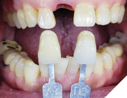
The patient then returned at 4 months to initiate the impression making procedure for the final screw retained restoration. The temp restoration was unscrewed, a well healed soft tissue emergence profile with adequate buccal volume of tissue was noted (Fig. 21). For the lab to recreate this emergence profile, a custom impression coping had to be fabricated to allow for capturing this soft tissue contour. The temp crown (Fig. 22) was screwed onto a lab analog (Fig. 23) and pressed into a glass dampen dish with a fast set PVS material (Fig. 24). Once the PVS had polymerized, the temp crown was unscrewed from the analog exposing the captured intaglios surface of the temp restoration (Fig. 25). A hexed open tray impression coping was then screwed back onto the lab analog (Fig. 26) and the flow composite was filled into the space created (Fig. 27) by the intaglio of the temp restoration. Once light cured, this impression coping was unscrewed and now have developed a custom impression coping (Fig. 28), which was then screwed back into the implant (Fig. 29) and a radiograph was taken to verify complete seating (Fig. 30). Fast set PVS was utilized and an upper open tray pick up impression with this custom impression coping was done, a lower PVS and bite registration was then made (Fig. 31). This was sent to the lab along with specific instructions along with shade tab photographs (Fig. 32).
Fig. 21
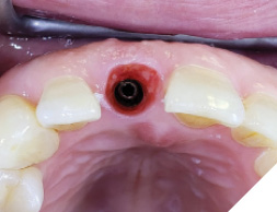
Fig. 22
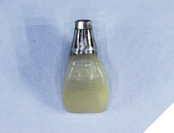
Fig. 23
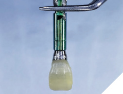
Fig. 24
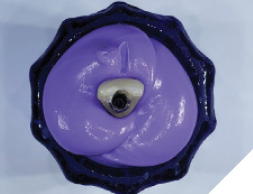
Fig. 25
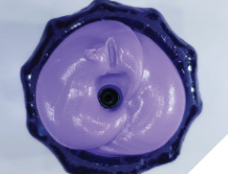
Fig. 26
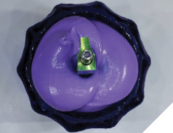
Fig. 27
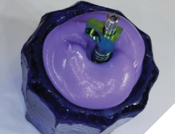
Fig. 28
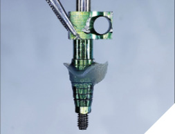
Fig. 29
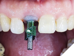
Fig. 30
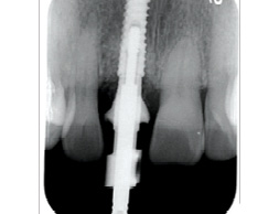
Fig. 31
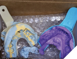
Fig. 32
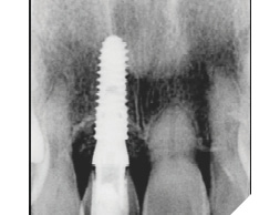
In 2 weeks, a screwmentable restoration-milled zirconia and custom titanium abutment was inserted (Fig. 33) occlusion and inter proximal contacts verified and an X-ray was taken for the final seating of the restoration (Fig. 34). Once can observe stable crestal bone levels at 4 months of healing.
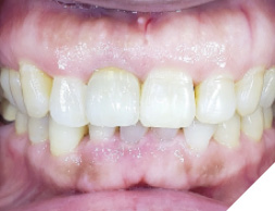
A 2 week follow up (Fig. 35) was done to confirm the patient had no concerns or issues with her new implant restoration. The patient was happy with the final outcome.
Fig. 33
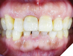
Fig. 34
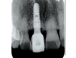
Fig. 35
Discussion
The immediate implant placement with provisionalization technique using the extracted tooth presented several benefits. Immediate placement of the implant allows for reduced treatment time and minimizes the potential for bone resorption associated with delayed placement. The use of the extracted tooth as a provisional restoration offers an aesthetic advantage by preserving soft tissue contours and providing the patient with an immediate aesthetic result.
The success of this technique depends on careful treatment planning, precise execution of the extraction, and the adaptability of the provisional restoration. In this case, the immediate provisionalization facilitated optimal soft tissue healing and aesthetic outcomes.
Conclusion
This case report demonstrates that immediate anterior dental implant placement with provisionalization using the extracted natural tooth can be a successful strategy for single-tooth replacement. It offers significant benefits in terms of esthetics, treatment time, and patient satisfaction. 
Oral Health welcomes this original article.
About the Author

Dr. Joshua Shieh is a third generation clinician and has been practising general dentistry in Ontario since 2015. Over the last eight years, he has earned his Diplomate of the American Board of Oral Implantology, Fellow of the International Congress of Oral Implantology and Fellow of the Academy of General Dentistry. A travelling surgical associate in the GTA with special interests in wisdom teeth, hard and soft tissue regeneration around teeth / implants, surgical implant placements and full arch implant rehabilitations. The author can be reached out via email: drjoshuashieh@gmail.com